
Loose Leaf for Engineering Circuit Analysis Format: Loose-leaf
9th Edition
ISBN: 9781259989452
Author: Hayt
Publisher: Mcgraw Hill Publishers
expand_more
expand_more
format_list_bulleted
Concept explainers
Videos
Textbook Question
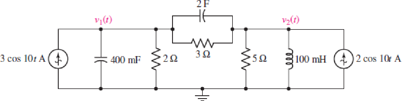
Chapter 10, Problem 47E
For the circuit depicted in Fig. 10.58, (a) redraw with appropriate phasors and impedances labeled; (b) employ nodal analysis to determine the two nodal voltages v1(t) and v2(t).
FIGURE 10.58
Expert Solution & Answer

Trending nowThis is a popular solution!

Students have asked these similar questions
A resistor'R' with resistance value of 24 ohm, an inductor 'L' with inductance 20mH, and a capacitor 'C' with capacitance 50 micro Farrad are connected in series with a AC voltage v(t) where v(t) = 50 cos (2 vt + 30 degrees) v. Determine the current i(t) and total impedance if the frequency f is
i. 60 Hz
ii. 400Hz
Consider the following figure.
A cos (10r +9°) V
252
www
cos(10t+
1 H
9) A.
330 mF
HE
Consider A = 6.000. Employ phasor analysis techniques to obtain expressions for the two mesh currents i and 2 shown in the given
figure. (Round the final answer to four decimal places.)
Report your answer so that all angles are in the range of 0 degrees to positive 180 degrees.
The value of (1) is
cos(10t+
°) A.
The value of 2() is [
5i₁
1. Fill in the table by converting the values into the equivalent forms. Unless otherwise specified, assume the frequency to be
60HZ. Consider that the table consists of voltage signal values across certain circuit components (i.e. phasor magnitudes
are expressed in RMS).
Rectangular Form
-5+j
Phasor Form
Time-Domain Function
10 cos (201 + 50°)
1420°
Chapter 10 Solutions
Loose Leaf for Engineering Circuit Analysis Format: Loose-leaf
Ch. 10.1 - Find the angle by which i1 lags v1 if v1 = 120...Ch. 10.2 - Determine values for A, B, C, and if 40 cos(100t ...Ch. 10.2 - Let vs = 40 cos 8000t V in the circuit of Fig....Ch. 10.3 - Prob. 4PCh. 10.3 - If the use of the passive sign convention is...Ch. 10.4 - Let = 2000 rad/s and t = 1 ms. Find the...Ch. 10.4 - Transform each of the following functions of time...Ch. 10.4 - In the circuit of Fig. 10.17, both sources operate...Ch. 10.5 - With reference to the network shown in Fig. 10.19,...Ch. 10.5 - In the frequency-domain circuit of Fig. 10.21,...
Ch. 10.5 - Determine the admittance (in rectangular form) of...Ch. 10.6 - Use nodal analysis on the circuit of Fig. 10.23 to...Ch. 10.6 - Use mesh analysis on the circuit of Fig. 10.25 to...Ch. 10.7 - If superposition is used on the circuit of Fig....Ch. 10.7 - Prob. 15PCh. 10.7 - Determine the current i through the 4 resistor of...Ch. 10.8 - Select some convenient reference value for IC in...Ch. 10 - Evaluate the following: (a) 5 sin (5t 9) at t =...Ch. 10 - (a) Express each of the following as a single...Ch. 10 - Prob. 3ECh. 10 - Prob. 4ECh. 10 - Prob. 5ECh. 10 - Calculate the first three instants in time (t 0)...Ch. 10 - (a) Determine the first two instants in time (t ...Ch. 10 - The concept of Fourier series is a powerful means...Ch. 10 - Household electrical voltages are typically quoted...Ch. 10 - Prob. 10ECh. 10 - Assuming there are no longer any transients...Ch. 10 - Calculate the power dissipated in the 2 resistor...Ch. 10 - Prob. 13ECh. 10 - Prob. 14ECh. 10 - Prob. 15ECh. 10 - Express the following complex numbers in...Ch. 10 - Prob. 17ECh. 10 - Prob. 18ECh. 10 - Evaluate the following, and express your answer in...Ch. 10 - Perform the indicated operations, and express the...Ch. 10 - Insert an appropriate complex source into the...Ch. 10 - For the circuit of Fig. 10.51, if is = 2 cos 5t A,...Ch. 10 - In the circuit depicted in Fig. 10.51, if is is...Ch. 10 - Employ a suitable complex source to determine the...Ch. 10 - Transform each of the following into phasor form:...Ch. 10 - Prob. 26ECh. 10 - Prob. 27ECh. 10 - The following complex voltages are written in a...Ch. 10 - Assuming an operating frequency of 50 Hz, compute...Ch. 10 - Prob. 30ECh. 10 - Prob. 31ECh. 10 - Prob. 32ECh. 10 - Assuming the passive sign convention and an...Ch. 10 - The circuit of Fig. 10.53 is shown represented in...Ch. 10 - (a) Obtain an expression for the equivalent...Ch. 10 - Determine the equivalent impedance of the...Ch. 10 - (a) Obtain an expression for the equivalent...Ch. 10 - Determine the equivalent admittance of the...Ch. 10 - Prob. 40ECh. 10 - Prob. 41ECh. 10 - Find V in Fig. 10.55 if the box contains (a) 3 in...Ch. 10 - Prob. 43ECh. 10 - Prob. 44ECh. 10 - Design a suitable combination of resistors,...Ch. 10 - Design a suitable combination of resistors,...Ch. 10 - For the circuit depicted in Fig. 10.58, (a) redraw...Ch. 10 - For the circuit illustrated in Fig. 10.59, (a)...Ch. 10 - Referring to the circuit of Fig. 10.59, employ...Ch. 10 - In the phasor-domain circuit represented by Fig....Ch. 10 - With regard to the two-mesh phasor-domain circuit...Ch. 10 - Employ phasor analysis techniques to obtain...Ch. 10 - Determine IB in the circuit of Fig. 10.62 if and ....Ch. 10 - Determine V2 in the circuit of Fig. 10.62 if and ....Ch. 10 - Employ phasor analysis to obtain an expression for...Ch. 10 - Determine the current ix in the circuit of Fig....Ch. 10 - Obtain an expression for each of the four...Ch. 10 - Determine the nodal voltages for the circuit of...Ch. 10 - Prob. 59ECh. 10 - Obtain an expression for each of the four mesh...Ch. 10 - Determine the individual contribution each current...Ch. 10 - Determine V1 and V2 in Fig. 10.68 if I1 = 333 mA...Ch. 10 - Prob. 63ECh. 10 - Obtain the Thvenin equivalent seen by the (2 j) ...Ch. 10 - The (2 j) impedance in the circuit of Fig. 10.69...Ch. 10 - With regard to the circuit depicted in Fig. 10.70,...Ch. 10 - Prob. 67ECh. 10 - Determine the individual contribution of each...Ch. 10 - Determine the power dissipated by the 1 resistor...Ch. 10 - The source Is in the circuit of Fig. 10.75 is...Ch. 10 - Prob. 72ECh. 10 - (a) Calculate values for IL, IR, IC, VL, VR, and...Ch. 10 - In the circuit of Fig. 10.77, (a) find values for...Ch. 10 - The voltage source Vs in Fig. 10.78 is chosen such...Ch. 10 - For the circuit shown in Fig. 10.79, (a) draw the...Ch. 10 - For the circuit shown in Fig. 10.80, (a) draw the...Ch. 10 - (a) Replace the inductor in the circuit of Fig....Ch. 10 - Design a purely passive network (containing only...
Knowledge Booster


Learn more about
Need a deep-dive on the concept behind this application? Look no further. Learn more about this topic, electrical-engineering and related others by exploring similar questions and additional content below.Similar questions
- 10. Two impedances consist of (resistance of 15 ohms and series-connected inductance of 0.04 H) and (resistance of 10 ohms, inductance of 0.1 H and a capacitance of 100 µF, all in series) are connectd in series and are connected to a 230 V, 50 Hz a.c. source. Find : (i) Current drawn, (ii) Voltage across each impedance, (iii) Individual and total power factor.arrow_forwardUnless given, use the: POLAR FORM for voltage and current, RECTANGULAR FORM for impedance. (30pts) Consider the following circuit, supplied by a 500mARMS current source with a 30° phase shift (i.e. Isource=500230⁰ mA). R1 100 Q L1 320 mH C1 16 μF a. What is the total impedance of the circuit? b. What is the voltage drop on the 100-ohm resistor, R1? c. Is the circuit inductive, capacitive, or neither (resistive)? d. Draw the phasor diagram of the voltage and current at R1. e. What is the total power (apparent) delivered by the current source? f. Draw the phasor diagram of the voltage and current at the source. 11 sine 50 Hz ellarrow_forwardConsider the phasor representation shown below of a circuit at 200 Hz for the following two subprob- lems. Vs=620° v -j4 2 Vo (a) Find the phasor voltage Vo in the circuit shown, and the corresponding voltage waveform vo(t) that Vo represents. (b) Suppose that the source Vg in the circuit is replaced with a new voltage source vs(t) = 6 cos(800rt), find the new phasor Vo and waveform vo(t).arrow_forward
- Consider a sinusoidal emf source, v(t) = Vm sin (@t) results of current of i(t) = Im sin (@t+0) is applied to circuit of R, L & C in series. How to find the voltage across each one?.arrow_forwardIn the circuit diagram given in the figure below, L=5 mH, C= 33.33 µF and R = 20 Q. For a voltage source v(t)=28.3cos(3000t+45°) V, determine: Choose.. + Magnitude of the total time Choose... + dependent current (A) Magnitude of the total phasor Choose... current (A) Phase angle of the total phasor current (Degrees) Choose... + Phase difference between total current and source voltage Choose... + (Degrees) Magnitude of the total Choose.. + impedance (ohms)arrow_forwardConsider the circuit diagram below. Compute a single equivalent impedance for this circuit for a source frequency of ? =40 Hz. Express your final answer as a phasor with polar coordinates. You must show your all your work for the complex math. Include a diagram of the equivalent circuit as part of your solution.arrow_forward
- Four circuit elements are connected in series across a sinusoidal alternating voltage given by 110 sin (ut +30°) The instantaneous voltage across three of the elements are given by v, = 30 sin wt, v, = 60 sin (wt+ 60°) and v, = 30 sin (wt- 30") %3D (a)Determine the expression for the fourth voltage in the form = A sin (wt + B) (b) What is the r.m.s. value of v?arrow_forwardUnless given, use the: POLAR FORM for voltage and current, RECTANGULAR FORM for impedance. Consider the following circuit, supplied by a 500mARMS current source with a 30° phase shift (i.e. Isource=500230⁰ mA). R1 L1 320 mH C1 16 μF a. What is the total impedance of the circuit? b. What is the voltage drop on the 100-ohm resistor, R1? c. Is the circuit inductive, capacitive, or neither (resistive)? d. Draw the phasor diagram of the voltage and current at R1. e. What is the total power (apparent) delivered by the current source? f. Draw the phasor diagram of the voltage and current at the source. 11 sine 50 Hz 100 ellarrow_forward70. Ideal inductors and capacitors are 90 degrees out of phase with each other. True False 71. Ideal inductors and resistors are 180 degrees out of phase with each other. True False 72. Impedance of a circuit can be represented or expressed in complex form. True Falsearrow_forward
- In the network in the figure below, V, is known to be 4245°. Find Z. 29 Q + -j10 12/0° v (+ Z (a) Find the real part of Z. (b) Find the imaginary part of Z. (a) Ohm (b) Ohmarrow_forwardSolve no.08 and show solutions. (Situation no.04 image below)arrow_forwardConsider the circuit diagram below. Using mesh analysis, compute the currents (a) IR1, (b) Iz1, and (c) Ic1. Express your final answers as phasors using polar coordinates with phase angles measured in degrees. Your solution should include the circuit diagram redrawn to indicate these currents and their directions. R1 400 N L1 500 mH vị(t) v2(t) C1 6 V 12 V 10 uF 60 Hz 60 Hz ww R2 200 Narrow_forward
arrow_back_ios
SEE MORE QUESTIONS
arrow_forward_ios
Recommended textbooks for you
 Introductory Circuit Analysis (13th Edition)Electrical EngineeringISBN:9780133923605Author:Robert L. BoylestadPublisher:PEARSON
 Delmar's Standard Textbook Of ElectricityElectrical EngineeringISBN:9781337900348Author:Stephen L. HermanPublisher:Cengage Learning
 Programmable Logic ControllersElectrical EngineeringISBN:9780073373843Author:Frank D. PetruzellaPublisher:McGraw-Hill Education
 Fundamentals of Electric CircuitsElectrical EngineeringISBN:9780078028229Author:Charles K Alexander, Matthew SadikuPublisher:McGraw-Hill Education
 Electric Circuits. (11th Edition)Electrical EngineeringISBN:9780134746968Author:James W. Nilsson, Susan RiedelPublisher:PEARSON
 Engineering ElectromagneticsElectrical EngineeringISBN:9780078028151Author:Hayt, William H. (william Hart), Jr, BUCK, John A.Publisher:Mcgraw-hill Education,
Introductory Circuit Analysis (13th Edition)
Electrical Engineering
ISBN:9780133923605
Author:Robert L. Boylestad
Publisher:PEARSON
Delmar's Standard Textbook Of Electricity
Electrical Engineering
ISBN:9781337900348
Author:Stephen L. Herman
Publisher:Cengage Learning
Programmable Logic Controllers
Electrical Engineering
ISBN:9780073373843
Author:Frank D. Petruzella
Publisher:McGraw-Hill Education
Fundamentals of Electric Circuits
Electrical Engineering
ISBN:9780078028229
Author:Charles K Alexander, Matthew Sadiku
Publisher:McGraw-Hill Education
Electric Circuits. (11th Edition)
Electrical Engineering
ISBN:9780134746968
Author:James W. Nilsson, Susan Riedel
Publisher:PEARSON
Engineering Electromagnetics
Electrical Engineering
ISBN:9780078028151
Author:Hayt, William H. (william Hart), Jr, BUCK, John A.
Publisher:Mcgraw-hill Education,
Nodal Analysis for Circuits Explained; Author: Engineer4Free;https://www.youtube.com/watch?v=f-sbANgw4fo;License: Standard Youtube License