
Mechanics of Materials, 7th Edition
7th Edition
ISBN: 9780073398235
Author: Ferdinand P. Beer, E. Russell Johnston Jr., John T. DeWolf, David F. Mazurek
Publisher: McGraw-Hill Education
expand_more
expand_more
format_list_bulleted
Concept explainers
Videos
Textbook Question
Chapter 1, Problem 68RP
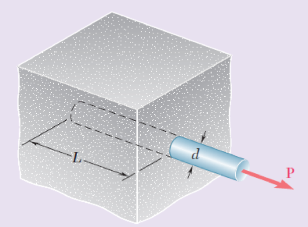
A force P is applied as shown to a steel reinforcing bar that has been embedded in a block of concrete. Determine the smallest length L for which the full allowable normal stress in the bar can be developed. Express the result in terms of the diameter d of the bar, the allowable normal stress σall in the steel, and the average allowable bond stress τall between the concrete and the cylindrical surface of the bar. (Neglect the normal stresses between the concrete and the end of the bar.)
Fig. P1.68
Expert Solution & Answer
Want to see the full answer?
Check out a sample textbook solution
Students have asked these similar questions
1. Determine the average normal stress in each of the 20-mm diameter bars of the truss. Set P = 40KN. If the average normal stress in each of the 20-mmdiameter bars is not allowed to exceed 150 MPa, determine the maximum force P that can be applied to joint C.
Three forces, each of magnitude P= 4 kN, are applied to the structure shown. Determine the cross-sectional area of the uniform
portion of rod BE for which the normal stress in that portion is +100 MPa.
0.100 m
IP IP
(O
D
360
IB
0.150 m 0.300 m
0.250 m
The cross-sectional area of the uniform portion of rod BE is
|mm2.
A 1000 kg homogenous bar 2 m long is suspended horizontally from two vertical cables A and B each 1.8 m long and connected at both ends. With cross-sectional area 400 mm sq. Determine the magnitude of the largest additional force acting downward which can be applied to the bar. The stresses in the cables A and B are limited to 100 MPa and 50 MPa respectively.
Chapter 1 Solutions
Mechanics of Materials, 7th Edition
Ch. 1.2 - Two solid cylindrical rods AB and BC are welded...Ch. 1.2 - Two solid cylindrical rods AB and BC are welded...Ch. 1.2 - Two solid cylindrical rods AB and BC are welded...Ch. 1.2 - Two solid cylindrical rods AB and BC are welded...Ch. 1.2 - A strain gage located at C on the surface of bone...Ch. 1.2 - Two brass rods AB and BC, each of uniform...Ch. 1.2 - Each of the four vertical links has an 8 36-mm...Ch. 1.2 - Link AC has a uniform rectangular cross section 18...Ch. 1.2 - Three forces, each of magnitude P = 4 kN, are...Ch. 1.2 - Link BD consists of a single bar 1 in. wide and 12...
Ch. 1.2 - For the Pratt bridge truss and loading shown,...Ch. 1.2 - The frame shown consists of four wooden members,...Ch. 1.2 - An aircraft tow bar is positioned by means of a...Ch. 1.2 - Two hydraulic cylinders are used to control the...Ch. 1.2 - Determine the diameter of the largest circular...Ch. 1.2 - Two wooden planks, each 12 in. thick and 9 in....Ch. 1.2 - When the force P reached 1600 lb, the wooden...Ch. 1.2 - A load P is applied to a steel rod supported as...Ch. 1.2 - The axial force in the column supporting the...Ch. 1.2 - Three wooden planks are fastened together by a...Ch. 1.2 - A 40-kN axial load is applied to a short wooden...Ch. 1.2 - An axial load P is supported by a short W8 40...Ch. 1.2 - Link AB, of width b = 2 in. and thickness t=14...Ch. 1.2 - Determine the largest load P that can be applied...Ch. 1.2 - Knowing that = 40 and P = 9 kN, determine (a) the...Ch. 1.2 - The hydraulic cylinder CF, which partially...Ch. 1.2 - For the assembly and loading of Prob. 1.7,...Ch. 1.2 - Two identical linkage-and-hydraulic-cylinder...Ch. 1.5 - Two wooden members of uniform rectangular cross...Ch. 1.5 - Two wooden members of uniform rectangular cross...Ch. 1.5 - The 1.4-kip load P is supported by two wooden...Ch. 1.5 - Two wooden members of uniform cross section are...Ch. 1.5 - A centric load P is applied to the granite block...Ch. 1.5 - A 240-kip load P is applied to the granite block...Ch. 1.5 - A steel pipe of 400-mm outer diameter is...Ch. 1.5 - A steel pipe of 400-mm outer diameter is...Ch. 1.5 - A steel loop ABCD of length 5 ft and of 38-in....Ch. 1.5 - Link BC is 6 mm thick, has a width w = 25 mm, and...Ch. 1.5 - Link BC is 6 mm thick and is made of a steel with...Ch. 1.5 - Members AB and BC of the truss shown are made of...Ch. 1.5 - Members AB and BC of the truss shown are made of...Ch. 1.5 - Link AB is to be made of a steel for which the...Ch. 1.5 - Two wooden members are joined by plywood splice...Ch. 1.5 - For the joint and loading of Prob. 1.43, determine...Ch. 1.5 - Three 34-in.-diameter steel bolts are to be used...Ch. 1.5 - Three steel bolts are to be used to attach the...Ch. 1.5 - A load P is supported as shown by a steel pin that...Ch. 1.5 - A load P is supported as shown by a steel pin that...Ch. 1.5 - A steel plate 14 in. thick is embedded in a...Ch. 1.5 - Determine the factor of safety for the cable...Ch. 1.5 - Link AC is made of a steel with a 65-ksi ultimate...Ch. 1.5 - Solve Prob. 1.51, assuming that the structure has...Ch. 1.5 - Each of the two vertical links CF connecting the...Ch. 1.5 - Solve Prob. 1.53, assuming that the pins at C and...Ch. 1.5 - In the structure shown, an 8-mm-diameter pin is...Ch. 1.5 - In an alternative design for the structure of...Ch. 1.5 - Prob. 57PCh. 1.5 - The Load and Resistance Factor Design method is to...Ch. 1 - In the marine crane shown, link CD is known to...Ch. 1 - Two horizontal 5-kip forces are applied to pin B...Ch. 1 - For the assembly and loading of Prob. 1.60,...Ch. 1 - Two steel plates are to be held together by means...Ch. 1 - A couple M of magnitude 1500 N m is applied to...Ch. 1 - Knowing that link DE is 18 in. thick and 1 in....Ch. 1 - A 58-in.-diameter steel rod AB is fitted to a...Ch. 1 - In the steel structure shown, a 6-mm-diameter pin...Ch. 1 - Prob. 67RPCh. 1 - A force P is applied as shown to a steel...Ch. 1 - The two portions of member AB are glued together...Ch. 1 - The two portions of member AB are glued together...
Knowledge Booster


Learn more about
Need a deep-dive on the concept behind this application? Look no further. Learn more about this topic, mechanical-engineering and related others by exploring similar questions and additional content below.Similar questions
- Assume that the magnitude of the vertical force P is 2.5 kN. Determine the stress at point A and Barrow_forwardDetermine the stresses at the points A and C of the rectangular cross-section of a short column that is exposed to a compressive load P (into the plane) of 4 kN applied at the point E.arrow_forwardGiven the plane element shown which is an element acted upon by combined stresses. a. Use Mohr's Circle to determine the maximum shear stress on the element b. Also, using Mohr's Circle determine the maximum normal stress on the element.arrow_forward
- Determine the maximum value of the force P (kN) that can be applied to member AD if the allowable stress is 200 MPa and the maximum upward displacement of point A is 3 mm. Use E=100 GPa The values of the cross-sectional area, and L1, L2, and L3 are given in table below for each student. P A L1 12 kN L2 9 kN L3 LI (m) (m) Student Cross-sectional area L2 L3 ID (mm?) (m) 1.45 1131731 200 3.8 1.2arrow_forwardTwo solid cylindrical rods (1) and (2) are joined together at flange B and loaded as shown. If the normal stress in each rod must be limited to 110 MPa, determine the minimum diameter d₂ required for rod (2). 140 KN 80 KN 140 KN O 30.7 mm O 52.5 mm 48.1 mm 61.4 mm 39.0 mm "вarrow_forwardDetermine the outer diameter (mm) of a tubular rod subjected to an axial force of 34 kN if it developed a stress of 50 MPa. Take note that the inner diameter is 1/6 of the outer diameter.arrow_forward
- The cantilever beam AB will be installed so that the 60-mm side forms an angle β between 0 and 90° with the vertical. The 660-N vertical force P is applied at the center of the free end of the beam. Determine the value of β for which the normal stress at point a is a maximum and the corresponding value of that stress. (Round the final answer to two decimal places.)arrow_forwardThe cross-sectional area of the bar ABCD is 600 mm². Determine the maximum normal stress in the bar?arrow_forwardThe rectangular bar has a width of w = 3.50 in. and a thickness of t = 1.50 in. The normal stress on plane AB of the rectangular block shown is 6 ksi (C) when the load Pis applied. Assume a = 4 and b = 5. Determine (a) the magnitude of load P. (b) the shear stress on plane AB. (c) the maximum normal and shear stresses in the block at any possible orientation. P B Answers: (а) Р- i kips (b) Tự = i ksi (c) Omax = i ksi Tmax i ksiarrow_forward
- Two solid cylindrical rods (1) and (2) are joined together at flange B and loaded as shown. The diameter of rod (1) is d₁ = 18 mm and the diameter of rod (2) is d₂ = 31 mm. Determine the absolute value of the normal stress in rod (2). 140 KN 80 KN (2) 140 KN A O 342 MPa O 368 MPa O 313 MPa O 281 MPa O 265 MPa Barrow_forward6kN and 1.0KNM loads are applied to the top of the 62-mm-diameter cast-iron as shown. Determine the principal stresses (max and min normal stresses), principal planes (orientation of plane for max-min normal stresses) and max shear stress by using Mohr's circle. Hint: Use given coordinate system. So, H is on x-z plane and K is on y- z plane 1.0 kN.m 6 kN X 220 mmarrow_forwardThe yoke-and-rod connection is subjected to a tensile force P. The end of the 40-mm diameter rod is embedded inside a wall at a length I of 100 mm using epoxy adhesive. If the allowable normal stress for the rods is 60 MPa, the allowable shear stress for the 25- mm diameter pin A is 50 MPa, and the allowable shear stress of the epoxy adhesive is 6 MPa, determine the largest force P that can be applied to the assembly. Note: Show your calculations for all types of stresses in detail. 40 mm 30 mm A 25 mm P.arrow_forward
arrow_back_ios
SEE MORE QUESTIONS
arrow_forward_ios
Recommended textbooks for you
 Elements Of ElectromagneticsMechanical EngineeringISBN:9780190698614Author:Sadiku, Matthew N. O.Publisher:Oxford University Press
 Mechanics of Materials (10th Edition)Mechanical EngineeringISBN:9780134319650Author:Russell C. HibbelerPublisher:PEARSON
 Thermodynamics: An Engineering ApproachMechanical EngineeringISBN:9781259822674Author:Yunus A. Cengel Dr., Michael A. BolesPublisher:McGraw-Hill Education
 Control Systems EngineeringMechanical EngineeringISBN:9781118170519Author:Norman S. NisePublisher:WILEY
 Mechanics of Materials (MindTap Course List)Mechanical EngineeringISBN:9781337093347Author:Barry J. Goodno, James M. GerePublisher:Cengage Learning
 Engineering Mechanics: StaticsMechanical EngineeringISBN:9781118807330Author:James L. Meriam, L. G. Kraige, J. N. BoltonPublisher:WILEY
Elements Of Electromagnetics
Mechanical Engineering
ISBN:9780190698614
Author:Sadiku, Matthew N. O.
Publisher:Oxford University Press
Mechanics of Materials (10th Edition)
Mechanical Engineering
ISBN:9780134319650
Author:Russell C. Hibbeler
Publisher:PEARSON
Thermodynamics: An Engineering Approach
Mechanical Engineering
ISBN:9781259822674
Author:Yunus A. Cengel Dr., Michael A. Boles
Publisher:McGraw-Hill Education
Control Systems Engineering
Mechanical Engineering
ISBN:9781118170519
Author:Norman S. Nise
Publisher:WILEY
Mechanics of Materials (MindTap Course List)
Mechanical Engineering
ISBN:9781337093347
Author:Barry J. Goodno, James M. Gere
Publisher:Cengage Learning
Engineering Mechanics: Statics
Mechanical Engineering
ISBN:9781118807330
Author:James L. Meriam, L. G. Kraige, J. N. Bolton
Publisher:WILEY
Everything About COMBINED LOADING in 10 Minutes! Mechanics of Materials; Author: Less Boring Lectures;https://www.youtube.com/watch?v=N-PlI900hSg;License: Standard youtube license