
Videos
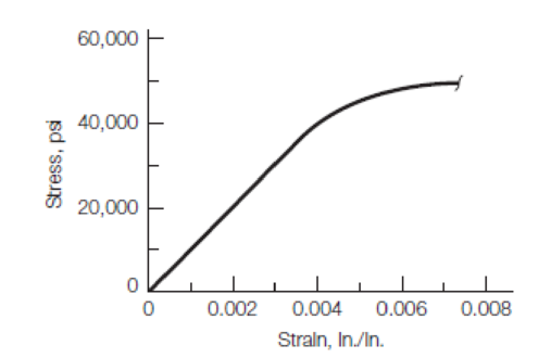
The stress–strain relationship shown in Figure P1.16 was obtained during the tensile test of an aluminum alloy specimen.
Determine the following:
a. Young’s modulus within the linear portion
b. Tangent modulus at a stress of 45,000 psi
c. Yield stress using an offset of 0.002 strain
d. If the yield stress in part c is considered failure stress, what is the maximum working stress to be applied to this material if a factor of safety of 1.5 is used?

Learn your wayIncludes step-by-step video

Chapter 1 Solutions
Materials for Civil and Construction Engineers (4th Edition)
Additional Engineering Textbook Solutions
Foundation Design: Principles and Practices (3rd Edition)
Java How to Program, Early Objects (11th Edition) (Deitel: How to Program)
Modern Database Management
Starting Out with C++: Early Objects (9th Edition)
Introduction To Programming Using Visual Basic (11th Edition)
Software Engineering (10th Edition)


- The results of a tensile test are shown in Table 1.5.2. The test was performed on a metal specimen with a circular cross section. The diameter was 3 8 inch and the gage length (The length over which the elongation is measured) was 2 inches. a. Use the data in Table 1.5.2 to produce a table of stress and strain values. b. Plot the stress-strain data and draw a best-fit curve. c. Compute the, modulus of elasticity from the initial slope of the curve. d. Estimate the yield stress.arrow_forwardThe data in Table 1.5.3 were obtained from a tensile test of a metal specimen with a rectangular cross section of 0.2011in.2 in area and a gage length (the length over which the elongation is measured) of 2.000 inches. The specimen was not loaded to failure. a. Generate a table of stress and strain values. b. Plot these values and draw a best-fit line to obtain a stress-strain curve. c. Determine the modulus of elasticity from the slope of the linear portion of the curve. d. Estimate the value of the proportional limit. e. Use the 0.2 offset method to determine the yield stress.arrow_forwardCompare the engineering and true secant elastic moduli for the natural rubber in Example Problem 6.2 at an engineering strain of 6.0. Assume that the deformation is all elastic.arrow_forward
- The elastic portion of the tension stress–strain diagram for an aluminum alloy is shown in the figure. The specimen used for the test has a gauge length of 2 in. and a diameter of 0.5 in. If the applied load is 10 kip, determine the new diameter of the specimen. The shear modulus is Gal = 3.8(103) ksi.arrow_forwardThe stress–strain relationship shown in Figure was obtained during the tensile test of an aluminum alloy specimen. Determine the following:a. Young’s modulus within the linear portionb. Tangent modulus at a stress of 45,000 psic. Yield stress using an offset of 0.002 straind. If the yield stress in part c is considered failure stress, what is the maximum working stress to be applied to this material if a factor of safety of 1.5 is used?arrow_forwardTesting a round steel alloy bar with a diameter of 15 mm and a gauge length of 250 mm produced the stress–strain relationship shown in Figure Determinea. the elastic modulusb. the proportional limitc. the yield strength at a strain offset of 0.002d. the tensile strengthe. the magnitude of the load required to produce an increase in length of 0.38 mmf. the final deformation, if the specimen is unloaded after being strained by the amount specified in (e)g. In designing a typical structure made of this material, would you expect the stress applied in (e) reasonable? Why?arrow_forward
- S Figure P1.16 shows the stress-strain relations of metals A and B during ten- sion tests until fracture. Determine the following for the two metals (show all calculations and units): a. Proportional limit b. Yield stress at an offset strain of 0.002 m/m. c. Ultimate strength d. Modulus of resilience e. Toughness f. Which metal is more ductile? Why? 900 Metal A 600 Metal B 300 0.00 0.02 0.04 0.06 0.08 0.10 0.12 0.14 Strain, m/m FIGURE P1.16 Stress, MPaarrow_forwardA steel alloy specimen having a rectangular cross section of dimensions 19.1 mm x 3.1 mm (0.7520 in. × 0.1220 in.) has the stress-strain behavior shown in the Animated Figure 6.22b. If this specimen is subjected to a tensile force of 98290 N (22100 Ib;) then (a) Determine the amount of elastic strain induced. (b) Determine the amount of plastic strain induced. (c) If its original length is 610 mm, what will be its final length after this force is applied and then released? The elastic modulus for steel is 207 GPa. (a) i (b) i (c) i mmarrow_forwardThe stress–strain relation shown in Figure was obtained during the tensile test of an aluminum alloy specimen. Determine the the maximum working stress to be applied to this material if a factor of safety of 1.5 is used?arrow_forward
- An aluminum alloy rod has a circular cross section with a diameter of 8 mm. This rod is subjected to a tensile load of 4 kN. Assume that the material is within the elastic region and E = 69 GPa. a. What will be the lateral strain if Poisson’s ratio is 0.33? b. What will be the diameter after load application?arrow_forwardA tensile test specimen of aluminum alloy having a diameter of 0.5 in. and a gage length of 2 in. was tested to fracture. The complete stress-strain diagram for this specimen is shown below to the left. The small strain portion of this diagram has been enlarged (to the right) to show in more detail the linear portion of the stress-strain diagram. Determine (a) Young's modulus or modulus of elasticity (i.e., the slope of linear portion), (b) yield stress (using the so-called 0.2% offset method from the lecture notes), (c) yield strain (i.e., the strain corresponding to yield stress, not the 0.2%!), (d) ultimate strength (i.e., the peak in stress-strain diagram), (e) rupture stress (i.e., stress at breaking/failure), (f) rupture strain (i.e., the strain corresponding to rupture stress). 80 70 70 60 60 50 50 40 30 30 20 20 10 10 0.005 0.01 0.015 0.02 Strain (in/in) Strain (in/in) Stress (ksi) 0.015 - 0.03 - 0.12 - 0.135 - 0.15 Stress (ksi)arrow_forwardThe elastic portion of the tension stress-strain diagram for an aluminum alloy is shown in the figure. The specimen used for the test has a gauge length of 2 in. and a diameter of 0.5 in. If the applied load is 10 kip, determine the new diameter of the specimen. The shear modulus is G al =3.811032 ksiarrow_forward
 Materials Science And Engineering PropertiesCivil EngineeringISBN:9781111988609Author:Charles GilmorePublisher:Cengage Learning
 Steel Design (Activate Learning with these NEW ti...Civil EngineeringISBN:9781337094740Author:Segui, William T.Publisher:Cengage Learning