Filler circuit. Figure 30–33 shows a simple filler circuit designed to pass dc voltages with minimal attenuation and to remove, as much as possible, any ac components (such as 60-Hz line voltage that could cause hum in a stereo receiver, for example). Assume V in = V 1 + V 2 where V 1 is dc and V 2 = V 20 sin ωt, and that any resistance is very small. ( a ) Determine the current through the capacitor give amplitude and phase (assume R = 0 and X L > X C ). ( b ) Show that the ac component of the output voltage, V 2 out , equals ( Q/C ) − V 1 , where Q is the charge on the capacitor at any instant, and determine the amplitude and phase of V 2 out . ( c ) Show that the attenuation of the ac voltage is greatest when X C ≪ X L , and calculate the ratio of the output to input ac voltage in this case. ( d ) Compare the dc output voltage to input voltage. FIGURE 30–33 Problems 91 and 92.
Filler circuit. Figure 30–33 shows a simple filler circuit designed to pass dc voltages with minimal attenuation and to remove, as much as possible, any ac components (such as 60-Hz line voltage that could cause hum in a stereo receiver, for example). Assume V in = V 1 + V 2 where V 1 is dc and V 2 = V 20 sin ωt, and that any resistance is very small. ( a ) Determine the current through the capacitor give amplitude and phase (assume R = 0 and X L > X C ). ( b ) Show that the ac component of the output voltage, V 2 out , equals ( Q/C ) − V 1 , where Q is the charge on the capacitor at any instant, and determine the amplitude and phase of V 2 out . ( c ) Show that the attenuation of the ac voltage is greatest when X C ≪ X L , and calculate the ratio of the output to input ac voltage in this case. ( d ) Compare the dc output voltage to input voltage. FIGURE 30–33 Problems 91 and 92.
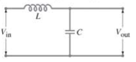
Filler circuit. Figure 30–33 shows a simple filler circuit designed to pass dc voltages with minimal attenuation and to remove, as much as possible, any ac components (such as 60-Hz line voltage that could cause hum in a stereo receiver, for example). Assume Vin = V1+ V2 where V1 is dc and V2 = V20sin ωt, and that any resistance is very small. (a) Determine the current through the capacitor give amplitude and phase (assume R = 0 and XL > XC). (b) Show that the ac component of the output voltage, V2 out, equals (Q/C) − V1, where Q is the charge on the capacitor at any instant, and determine the amplitude and phase of V2 out. (c) Show that the attenuation of the ac voltage is greatest when XC ≪ XL, and calculate the ratio of the output to input ac voltage in this case. (d) Compare the dc output voltage to input voltage.
When an AC voltage source, with a maximum voltage of 200 V, is connected across a 50 Ω resistor, the power dissipated in the resistor is?
A circuit consists of a capacitor and resistor in series with an AC voltage source, as shown.
If VAC max = 40 V, R = 1.2 k2, C = 2.0 µF, and the frequency of the AC voltage source is f = 60 Hz, what is the average power dissipated in the
%3D
circuit?
C
O 0.9W
O 0.3W
O 30W
О 5.3W
O None above
Subm
An ac voltmeter, which displays the rms voltage between the two points touched by its leads, is used to
measure voltages in the circuit shown in Figure 24-36. In this circuit, the ac generator has an rms
voltage of 9 00 V and a frequency of 25 0 kHz. The inductance in the circuit is 0 250 mH, the capacitance
is 0 150 uF, and the resistance is 2 50 2 What is the reading on a voltmeter when it is connected to
points A and B
Chapter 30 Solutions
Physics for Scientists and Engineers with Modern Physics
Need a deep-dive on the concept behind this application? Look no further. Learn more about this topic, physics and related others by exploring similar questions and additional content below.


 Glencoe Physics: Principles and Problems, Student...PhysicsISBN:9780078807213Author:Paul W. ZitzewitzPublisher:Glencoe/McGraw-Hill