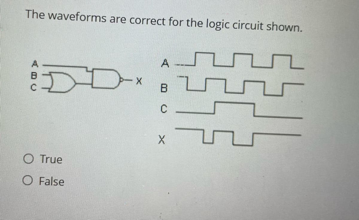
The waveforms are correct for the logic circuit shown. ADC X A B C O True O False X


Q: Solve for the output voltage, Vo (+), for t>o in the following transient circiut, after the switch…
A:
Q: An electromagnet has a movable iron part and dimensions of magnetic circuit with uniform cross…
A: a) R= 1697652.73 H-1, L= 9.694 mHb) flux= 70.69 micro Wb, flux density= 0.118 T, field intensity of…
Q: Good evening, Guidance on this please. Thanks!
A: Given data: -load 1−120 KVA at 0.8PF lag (wye connected)load 2−180 KVA at 0.7PF lag (wye…
Q: 5. In a three-phase circuit, if a fuse is lost and voltage is lost in phase 1, what must be true…
A: 5. In a three-phase circuit, if a fuse is lost and voltage is lost in phase 1, what must be true…
Q: a) Draw the pneumatic circuit of the system b) Built and run the pneumatic circuit in your FESTO
A: Given parameters the gates is to be opened or closed by means of 4 pushtwo being inside and two…
Q: The amplitude of a random signal is uniformly distributed between -5 V and 5 V. If the signal to…
A: The given data is drawn below:
Q: A battery bank needs to store at least 2300 Wh of energy at 56 V outside where the ambient air…
A: According to the question,Battery capacity = 18 Ah at 10 VRequired battery bank =2300 Wh at 56 V
Q: find V1, V2, v3, V4 -j2 Ω 22-30° Α V 4 1-j3 Ω 3 Ω j2 Ω (+1 งา 2 6230° V 2-j Ω 2 Ω V 3
A: Given circuitwe use supernode analysis.
Q: Digital Signal Processing I Determine the period (c) FUIPAMENTAL FREQUENCY (w) AND CALCULATE FOURIER…
A: Since you have posted multiple questions, we will provide the solution only to the first question as…
Q: Design a full adder using two half-adders.
A: In the given question we need to calculate the full adder using half adder .
Q: 32. 4.32 Implement the following Boolean function with a multiplexe 1. (a) F (A, B, C, D)=(0, 2, 5,…
A: Here we have boolean function and asked to implement the function using multiplexer.
Q: 4.40 Develop a block-diagram representation for the circuit in Fig. P4.40 for Us₂ = Us3 = 0 and *(a)…
A: The given data can be calculated as follows:
Q: A quarter-wave transmission line is used to match a 25 $2 load to a 75 $2 generator, i.e. the input…
A: The answer can be solved as shown in the below explanation. Explanation:(a) Calculate the physical…
Q: Q.5. Show that the group velocity can be written as: g n ελ 312 n² dλ
A: Group velocity is a concept in wave mechanics that describes the velocity at which the shape or…
Q: In the given circuit, &₁ = 15 V, &2 = 5 V and 83 = 10 V. The resistance of each resistor is 102.…
A: The circuit diagram,
Q: Determine the voltage across the inductor. write the same in sinusoidal form. 0163 R L 102 16 sim…
A: The given circuit isWe need to determine the voltage across the inductor, vL(t).
Q: V₁(t) + R1 www ix(t) C₁ R₂ Given the element values v₁ (t) = 18cos(210³t) V, R1 = 700 £2, R2 = 1400…
A: The given circuit isR1=700 Ω.R2=1400 Ω.C1=120 nF.The supply voltage is⇒v1(t)=18cos(2π103t), V.We…
Q: Part A An acb sequence balanced three-phase Y-connected source supplies power to a balanced…
A: The source voltage of phase a,The per phase line impedance, The load impedance per phase,
Q: 1) We need both of sin and cos for signal representation, why? 2) What are the values of ao, an and…
A: 1) We need both of sin and cos for signal representation, why?2) What are the values of ao, an and…
Q: CUSUM Analysis
A:
Q: 3.2. Using complex notation, combine the expressions to form a single sinusoid for each of the cases…
A: Sinusoidal waveform, often referred to as a sine wave, is a mathematical curve that describes a…
Q: 1. Given the following circuit: V1 -10V R1 w 3.Q R2 w 5Ω Determine: 1. R1, R2, R3, IR4, IRS 2. VR1,…
A: In this question, we need to determine the currents in each resistances , voltage across the each…
Q: Match the nodal equations TO THE CORRECT NODE NUMBER based on on the two figures (a, and b) provided
A: The given circuit diagram is shown below,
Q: Apply the superposition principle to the figure shown below. 6 A 40 10 Ω 20 Ω 4/ 30 V Based on the…
A: The current source will be open when voltage source is active and voltage source will be short when…
Q: Find V0 please answer in typing format solution
A: In the given circuit the value of the unknown voltage needs to be calculated. The voltage can be…
Q: A conductor of length = 1 m with a current = 60 A is placed perpendicularly to the field lines in a…
A: The magnitude of electromagnetic force on the wire is, Fmag=36.0NExplanation:Step 1:Step 2:
Q: 3.2
A: Detailed solution of the problem is attached below,Feel free to comment if you want any further…
Q: Solve the following circuit for I. using Thevenin's Theorem. 4k2 www 4v ② 4 KR√10 ↑ 4mA 2V
A: In this question, we need to determine the current Io using the Thevenin equivalent theorem.
Q: find the convolution of the unit impulse f(t) =u(t) -u(t-1) with itself
A:
Q: Show Step by step how Kv √ 글. 120.52 250 250 goes to Kv= l 1+Wx0.003 using 11+jl = x+yj = √x²² 1+ 2…
A:
Q: V 2 R2 R₁ 0 ww 3 ala Ia Ra 7 6 A B 5 Determine the voltage drop (in volts) from A to B for the…
A: The circuit diagram,
Q: Please show how it would look on that graph please use the given graph
A: Given minterms are Given graph is,Asked to show how it would look on that graph.
Q: Using nodal analysis, find v₁ and v2 in the circuit of Fig. 10.3. 25 cos (2t) A 292 Figure 10.3 0.2…
A: Kirchhoff's Current Law (KCL) is one of the fundamental laws in electrical engineering used to…
Q: Help me solve this question
A: 36.923mWExplanation:Step 1: General formula for power absorbed by resistor is given as: P=I2RHere…
Q: Question 4 f we have two capacitors that contribute to the upper cutoff frequency and the frequency…
A: The higher cutoff frequency of the amplifier needs to be selected from the given frequencies.
Q: Three friends decided to connect their individual car batteries in parallel using ideal cables…
A: current will be supplied by their parallel combination: 59.3592A Thevenin voltage of the parallel…
Q: I understand the entire solution for this question except for the choice of setting A as -1/3 why do…
A: In summary, setting A=−31 is necessary to cancel out the term e2t in the inverse Laplace transform,…
Q: Problem 3: Question Consider the circuit diagram below. If two identical capacitors, each with a…
A:
Q: What are the expected readings of the following in the figure below? (R = 7.200, AV = 5.30 V) www…
A: According to question, we need to calculate the voltmeter and ammeter value.
Q: Problem 3. Logic Diagram of a tiny ALU with DFF Accumulator This problem involves building a tiny…
A: According to the question, we need to create a 4-bit register using 4 D FFs which acts as an…
Q: An oscilloscope is to be have an in resistance of 8Mr, a sensitivity of and attenuation factory…
A: The attenuation resistance, also known as the input impedance, of an oscilloscope refers to the…
Q: (a) Determine the I-V characteristics equation at terminals a-b. Draw the approximate graph from the…
A: Given circuit is,Asked to determine the I V characteristics of the above circuit,Draw the simplest…
Q: 2.5
A: New capacitance is 601 pF.Explanation:
Q: Consider a lossless transmission line of length 1 = 0.62 with a characteristic impedance Zo=50 Q2…
A:
Q: Determine the power delivered to the load if the waveform of Figure 25-5 is applied to a 200-2…
A: The given data is shown below:
Q: 4.25 Construct a 5-to-32-line decoder with four 3-to-8-line decoders with enable and a 2-to-4-line…
A: According to the question, we need to construct a 5-to-32-line decoder with four 3-to-8-line…
Q: Find Fourier coefficient
A: Given:To find:Fourier series of the given signal.
Q: Solve problems by solving ana explaining eeach step
A: (a) v=48V(b) P=374.4W Please comment if you have any doubts. I will reply asap.Explanation:
Q: The inductor L₁ in the circuit shown in Fig. P13.84 is carrying an initial current of p A at the…
A: The inductor L1 carry the initial current and inductor L1 current is i1 and inductor L2 current is…
Q: what is the DTFT of sin(n)/n
A:

Step by step
Solved in 3 steps with 3 images


- Design a logic circuit to give an output: x = ( A'B' + A'C) • ( A'C' + C') with clear steps and explaination pleaseBuild the logic circuit for the function F1 = XYZ + YŽ + YZ using PALCreate a logic diagram out of this boolean expression. CD+BD+BC+AD+AC+AB Note: All inputs A B C and D must be together.
- Create a logic diagram out of this boolean expression. B'D+C'D+AB'+BCD' Note: All inputs A B C and D must be together.Construct the logic circuit (in DIG file) and construct the circuit’s truth table:i) Minimize the logic expression Y = BC + AC + AB using Boolean Algebra rules (Pleaseshow the steps). ii) Draw the simplified logic circuit based on the minimum expression obtained from (i).
- 8) Draw a logic circuit to implement the Boolean function F and with only NOR gates (AC+AB+BC)F(A,B,C,D) = (B'+D')(A+C'D)+BCD' 1. Find Minterms and Maxter, in short notation 2. Draw logic diagramUsing logic gates, implement the following Boolean functions. a. F(A,B,C) = AC + B’C + BC’ ( AS SUM OF PRODUCTS)