For the circuit shown, let Vcc = 3.3V, RE = 500 Ω, RC = 4 kΩ, R1= 85 kΩ, R2 = 35 k Ω, and β = 150 Using approximation, determine the Q-point parameters: IBQ, ICQ, and VCEQ. Indicate the exact numerical values, following the given unit.
For the circuit shown, let Vcc = 3.3V, RE = 500 Ω, RC = 4 kΩ, R1= 85 kΩ, R2 = 35 k Ω, and β = 150 Using approximation, determine the Q-point parameters: IBQ, ICQ, and VCEQ. Indicate the exact numerical values, following the given unit.

Delmar's Standard Textbook Of Electricity
7th Edition
ISBN:9781337900348
Author:Stephen L. Herman
Publisher:Stephen L. Herman
Chapter29: Dc Generators
Section: Chapter Questions
Problem 16RQ: Explain the difference between cumulative- and differential-compounded connections.

Related questions
Question
For the circuit shown,
let Vcc = 3.3V, RE = 500 Ω,
RC = 4 kΩ, R1= 85 kΩ,
R2 = 35 k Ω, and β = 150
Using approximation, determine the Q-point parameters: IBQ, ICQ, and VCEQ. Indicate the exact numerical values, following the given unit.
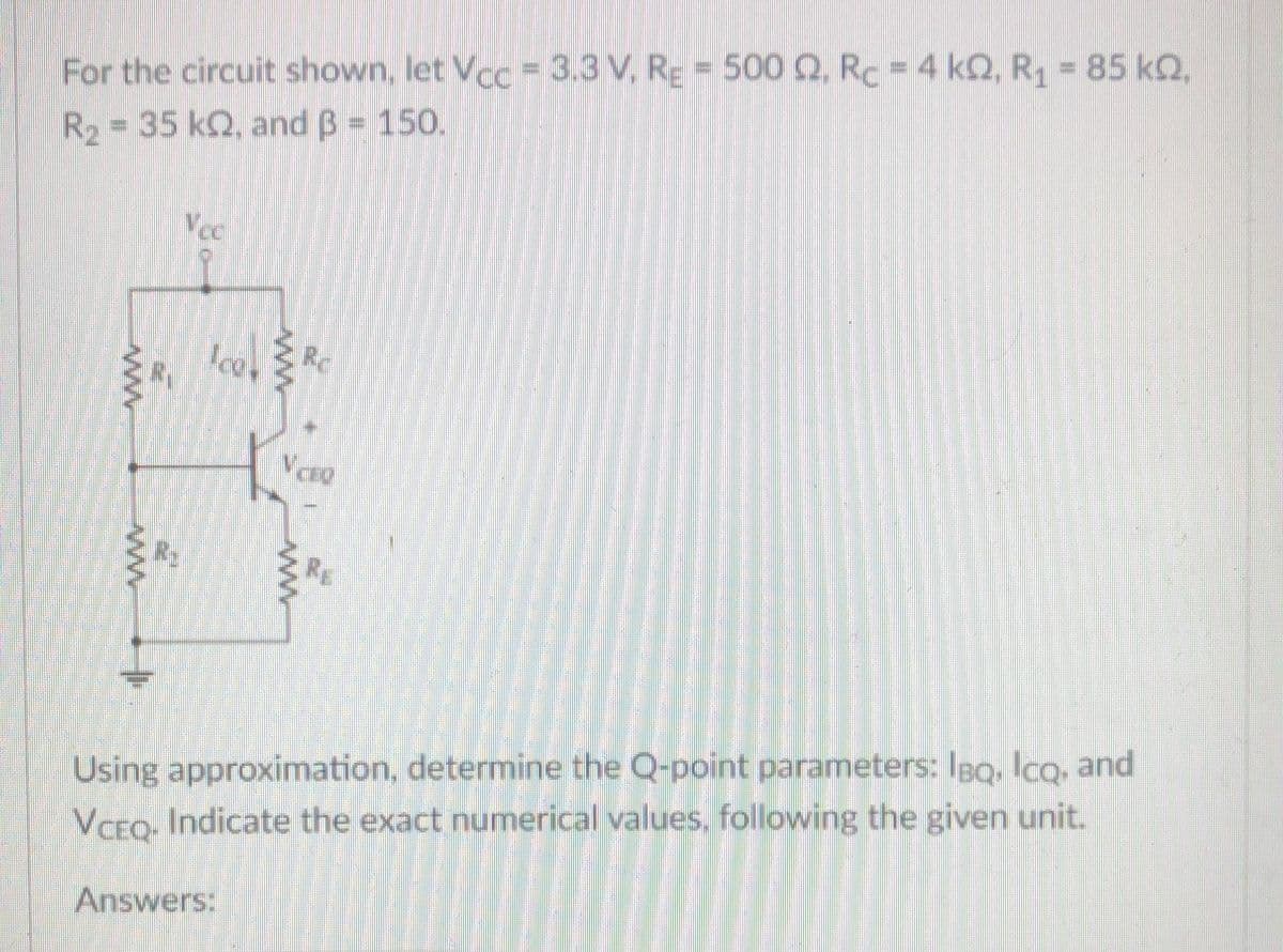
Transcribed Image Text:For the circuit shown, let Vcc = 3.3 V, RE = 500 Q. Rc = 4 kQ, R1 85 kQ,
R2 = 35 k2, and B = 150.
%3D
Vcc
Ice, Rc
R2
Using approximation, determine the Q-point parameters: IBQ, lcq, and
VCEQ, Indicate the exact numerical values, following the given unit.
Answers:
Expert Solution
This question has been solved!
Explore an expertly crafted, step-by-step solution for a thorough understanding of key concepts.

This is a popular solution!

Trending now
This is a popular solution!

Step by step
Solved in 2 steps with 2 images

Recommended textbooks for you
Delmar's Standard Textbook Of Electricity
Electrical Engineering
ISBN:
9781337900348
Author:
Stephen L. Herman
Publisher:
Cengage Learning
Delmar's Standard Textbook Of Electricity
Electrical Engineering
ISBN:
9781337900348
Author:
Stephen L. Herman
Publisher:
Cengage Learning